
Fleet 27 Rigging Topics, Comments, Observations
While the Etchells has only 3 sails, you will quickly find that it can be a very technical boat, with many control lines for precise adjustment of sail trim. Anyone who is new to racing the Etchells is best advised to keep things simple and focus first on boat handling and basic race management (starts, mark rounding, finding clear air, etc.). Just get the rig set up in a workable (base) setting and focus on sailing the boat around the course. As these tasks become more automatic, the numerous rig and sail trimming controls will begin to be more important.
Download the Sailmaker’s Tuning Guides
You will find that the major sailmakers (Doyle, North, etc.) each have tuning guides on their websites to guide you in setting up the rig best for their sails. Pick the tuning guide associated with the mainsail that you race with, and start with those settings. But, also read the other sailmaker’s tuning guides, as well, because there are useful pearls of wisdom in each of them that will begin to make sense as you get more experience racing the boat.
2019 Worlds Championships – Follow Up
Click to open: 2019 Etchells Worlds: Insights into a magic campaign
Andrew Palfrey’s Observations from 2018 World Championships
Andrew Palfrey is a well travelled professional racer and World Champion Etchells crew. He also gives back as a class governor. Here are his observations about the top 12 boats at the 2018 World Championships in Brisbane, AUS.
Click to open: Andrew Palfrey’s Survey of Top 12 at 2018 World Championships
Pearls of Wisdom
(Read this ashore before you contemplate adjusting your rig while racing)
Tuning the Mast Position & Setting Shroud Tensions
Etchells tuning is based around the concept of establishing a base setting for the rigging. These settings can be for any set of conditions you select, but it makes sense to establish the base setting for the predominant conditions that you race in, for example:
- Wind speed: 10 knots,
- Sea state: flat water,
- Crew weight: your usual, and
- Sails: your usual racing sails.
Adjustments are made for other wind/wave/crew weight/etc. conditions. You should return the boat to the base setting after racing. Here is a checklist of boat tuning steps to get a boat set up to a base condition. If you have items to add, include them in a comment (below).
- Adjust the mast step to correct base position fore and aft (North and Doyle each describe slightly different methods… pick the one for the brand of mainsail being used)
- Block mast at partners (deck) side-to-side, if not already done
- Verify shrouds are pinned in the correct chainplate holes (upper @ #2 and lower @ #4 aft of forward edge of chainplate)
- Adjust forestay length to base (maybe 48”). I suspect the base number you use might vary from this number, depending on whether your boat is a “heritage” boat (pre-#800 with original keel), is an older boat but with a retrofitted new-style keel, or is truly one of the post-#1000 modern boats. Establish your base length by trying to achieve a slight weather helm (Jud says 0 to 3 lbs on the tiller).
- Center the mast athwartships at the hounds (point where upper shrouds attach to the mast) (use tape measure pulled up on jib halyard – as close as you will get without a laser.)
- Adjust forestay tension to a nominal low setting (maybe 8 on Loos) by adjusting backstay tension
- Begin to tighten shroud tensions, while centering mast at hounds and straightening mast column; start with uppers, then adjust lowers.
- Set both uppers to base (~18 or 20 on Loos); recheck that mast hounds are centered in boat, port and starboard
- Set lowers to base (maybe ~12 on Loos); check that mast is in column
- Recheck that mast is centered and straight; adjust as necessary. Take the time necessary to get the mast centered and in column. This is important.
- Mark deck with an arrow for direction to rotate turnbuckles to tighten shrouds.
- (Even though tape is not permitted on an Etchells) Tape all ring-dings!!!
- Some other things that should be checked are:
- Spreader angles and swing
- Mark backstay adjustment extremes
- Measure/mark jib block positions (distance from jib tack)
- Ensure sheeting angle (track/jib block location) is as close to cuddy as possible
- Ensure jib halyard length/jib luff length works with base mast rake. May need to adjust something somewhere if mast rake was changed significantly
- Fraculator rigged?
- Windex and tell tales?
- etc. etc. etc.
FYI – Effect of Headstay Length on Mast Rake
I think getting the mast rake correct in your boat is extremely important to your upwind speed. Too much helm (i.e., too much rake), and you are just dragging your rudder as a brake on speed; too little, and you don’t point. It has taken me several years to figure it out for the Etchells, and I still am learning. If you have more than a little weather helm (if your tiller angle is more than 3 to 4 degrees or it takes two hands on the extension to steer upwind in 12-14 knots), take some rake out. It is a very fine adjustment, 1/4 inch of headstay length change does make a noticeable difference.
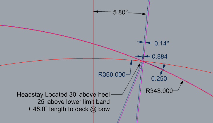
Headstay length is nominally 48 inches, ±1/2 inch (measured to the reference mark applied to the headstay IAW the sailmaker’s tuning guides), with shorter lengths in heavy wind (i.e., less mast rake), and longer lengths for light winds (i.e., more mast rake). 5/16″ diameter turnbuckle barrels are 24 threads per inch (i.e., 5/16 UNF thread), so 6 turns of the headstay pennant is 1/4 inch change in headstay length. (Note, see this post for a tip on making the headstay adjustable from above deck without removing the clevis pin.)
I was curious how much the mast rake changes with a 1/4″ change in headstay length (6 full turns of the headstay pennant). This layout sketch closely approximates the headstay and mast geometry at the top of the headstay. The headstay attachment point moves fore or aft 0.88 inches (a 0.14° mast rake angle change) with a 1/4″ change to the headstay length.
So, about a 3.5 : 1 ratio for the unit change in headstay position per unit change in headstay length.
Another way to look at this, over the full ±1/2 inch range of headstay adjustment (47.5″ — 48.5″), the headstay attachment point moves approximately ±1.8″, or 3.5″ total movement.
Control Lines and Rigging Adjustments
Below is a list of control lines and rigging adjustments often (but not always) used on an Etchells. If you know of other ones that should be added, submit them in a comment to this article. (Needs updating for boats with dog tracks. — eds)
- Mainsheet (Course)
- Mainsheet (Fine)
- Mainsail Traveller Control
- Main Halyard
- Mainsail Cunningham
- Boom Vang
- Mainsail Outhaul
- Jib Sheet (Course)
- Jib Sheet (Fine)
- Jib Car Position (Forward Purchase)
- Jib Sheet Barber Haul (in)
- Jib Cloth Tension
- Fraculator
- Jib Halyard
- Jib Halyard (Fine)
- Mast Position at Partners w/ Ram
- Mast Ram (Aft)
- Mast Ram (Fwd)
- or w/ Mast Partner Blocks
- Forward Mast Pull
- Aft Mast Pull
- Mast Block (Retract & Deploy)
- Forestay
- Shrouds
- Backstay (Course)
- Backstay (Fine)
- Spinnaker Halyard
- Spinnaker Sheets (Port & Starboard)
- Spinnaker Sheet Twing Lines
- Spinnaker Pole Topping Lift
- Spinnaker Pole Downhaul
- Spinnaker Bin (Deploy & Retract)
- Manual Bilge Pump (Stroke and Retract)
- Mid-Crew Hiking Safety Line
Fleet 27 Rigging Approaches
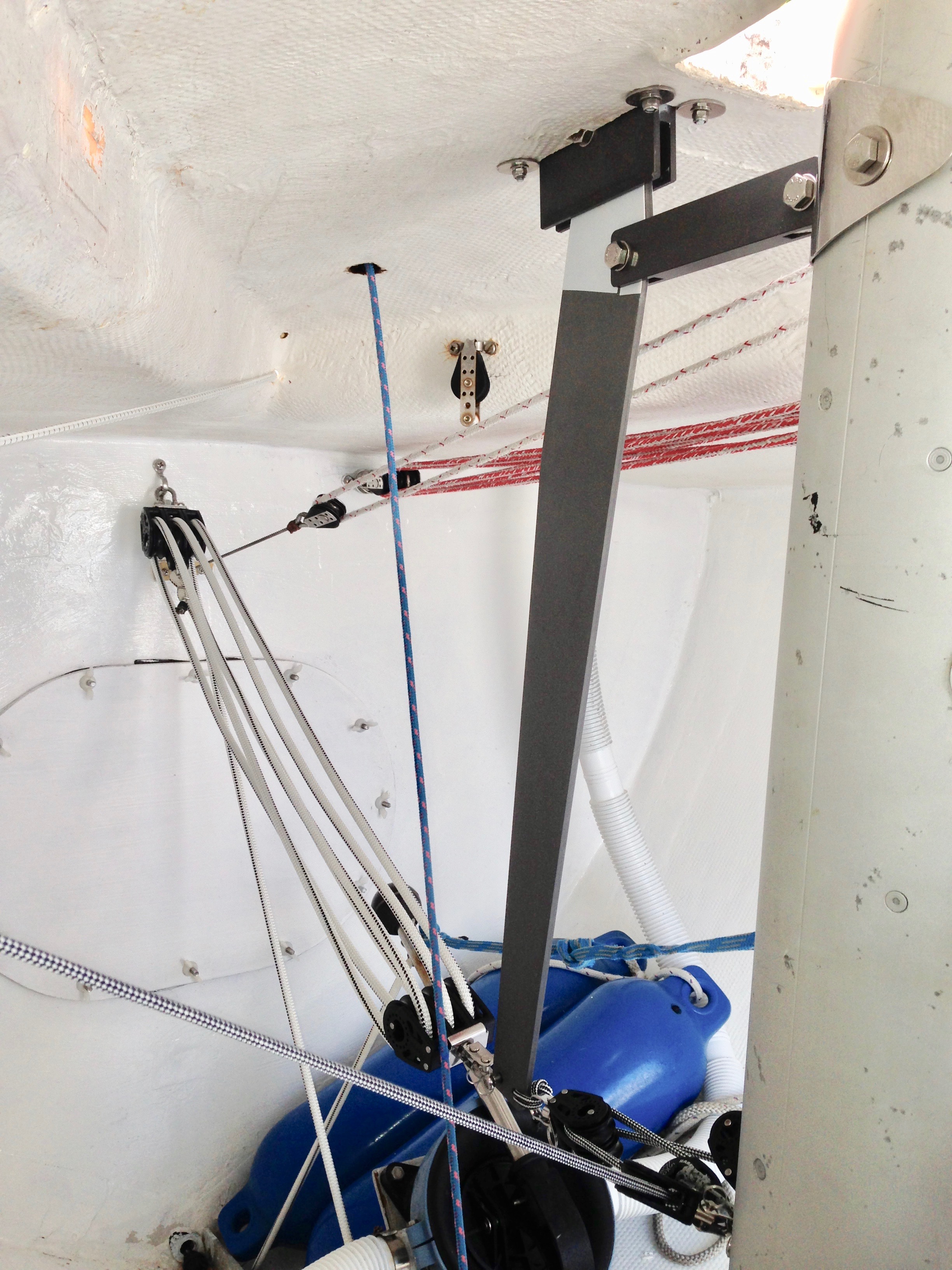
There are countless ways to rig the numerous control lines on an Etchells; the key is to make the controls accessible to the crew in their normal sailing position(s), as well as easy to operate. APS has many photos showing some different approaches, although the APS photos are a few years old, and rigging styles do evolve, especially when new control systems (like the mast ram) are introduced. Here we will present photos of the rigging on some of the boats of Fleet 27.
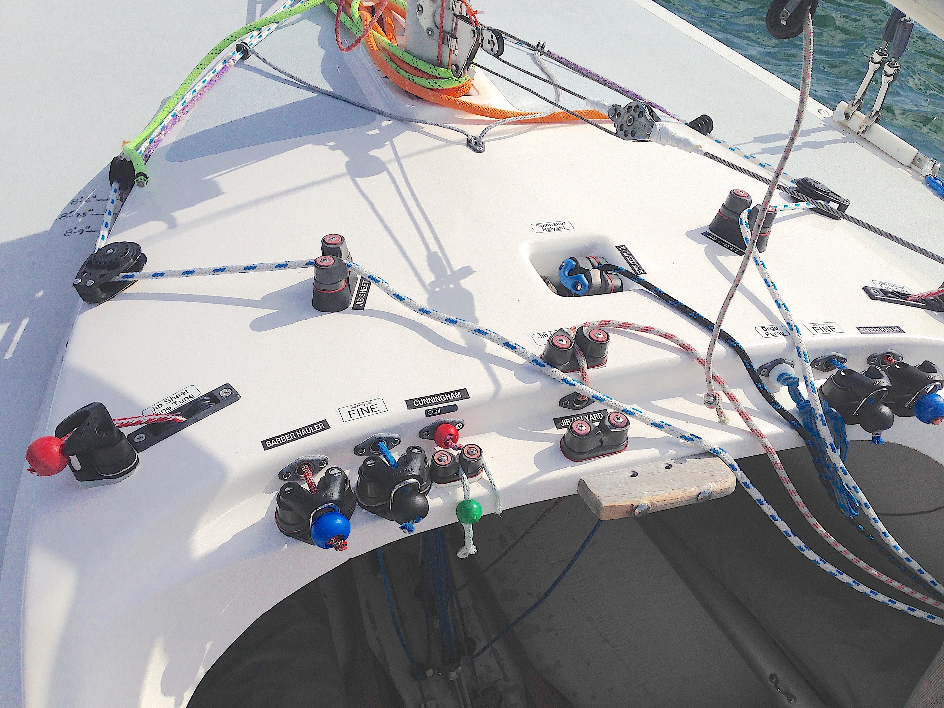
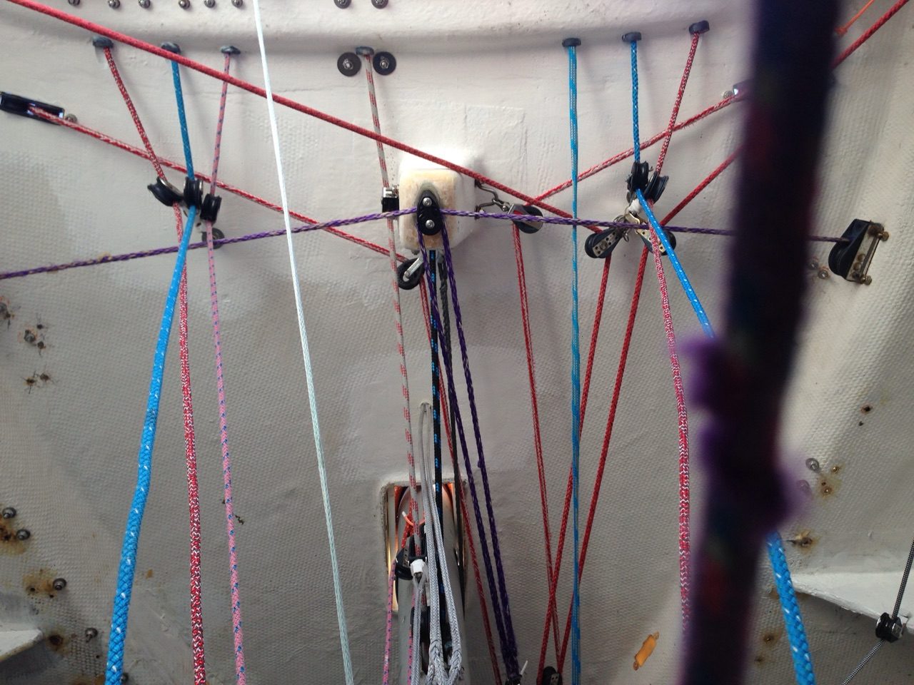
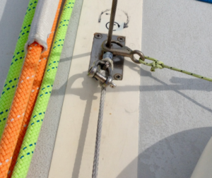
Looking up at the underside of the cuddy (Figure 2), many control lines a run under deck. Providing a fair lead for all these lines to the outside crew position is the biggest challenge. Boats that employ a mast ram have even more challenge to provide the ram with a clear volume forward of the mast in which to operate. The underside of the spinnaker cleat pocket provides an opportune mounting base to lead many of the control lines out to the crew. Also, eyestraps attached underneath the jib sheet cam cleats (using the same bolts used by the topside cleats) provide suitable anchoring points to attach multiple lead blocks with soft strops/ties, yet avoid drilling holes in shell.
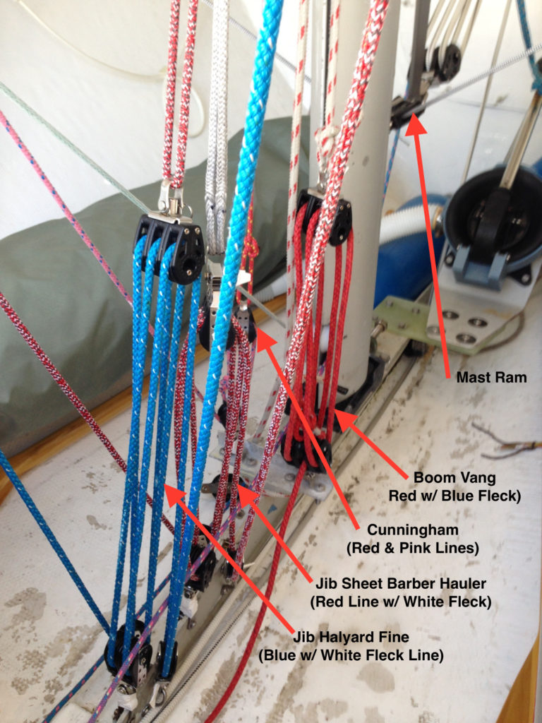
Several control purchases are anchored to the aluminum mast support beam.
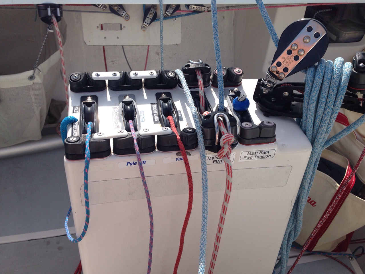
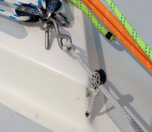
Position controls selected for the center center console so both mid-crew and helmsman can reach them. Each boat crew selects which controls are led here, and which controls are led to the cuddy bridge area, or to the side deck. Here, the mast ram forward tension shock cord is run to the console; six to eight feet of cord is pulled in when racing to provide pre-tension to the forward pull of the ram.
Jib Barber Inhaul
The link opens up an old article on the Jib Inhaul written by Alex Camet of North Sails covering installing and using a jib barber (in)haul on the Etchells.
Reportedly, Steve Benjamin currently uses barber inhaulers with 2 friction rings spliced to the end of each barber inhaul line, so apparently he pulls both parts of the jib sheets inboard. But, reportedly he has a unique jibsheet arrangement that possibly supports that approach better.
I think using a single friction ring around only one part of the jibsheet tackle, set up to pull in on the mostly static fine-trim side of the jibsheet tackle works ok. In heavy air, the barber hauler will be slack, so no additional friction from the in-haul ring is added to the fine-trim side. Light/medium air is when the barber hauler is used, and the added friction on the fine-trim side is not a burden (in theory).
Update 2022… The trend is towards the Aussie sail style, with a tighter headstay, jibs cut with draft further forward, and lots of jib sheet inhaul needed to trim the new jib correctly. Andrey Palfrey offers his Dog Tracks jib tracks to provide inhaul adjustment, Doyle has there double canted track system, and you can use rope inhaul schemes, as well.
Mast Ram
Professional sailor and coach Andrew “Dog” Palfrey developed and sells an Etchells mast ram direct from his Cowes, UK office. Also, Ezra Culver in Miami usually stocks Andrew’s mast rams. The mast ram in this photo is rigged in a style often seen in the Dragon class, using a multi-part shock cord purchase to pre-load the forward pull tension. The “Dragon” arrangement allows a single control line to adjust the mast position both forward and aft. However, many crews prefer to have separate forward and aft control lines.
Boom
In my view, the boom on an Etchells is way undersized for the way we sail boats these days. But, it is what it is. If you have the need to replace your boom, the rules permit a 1.3 meter long doubler sleeve inside the boom to help prevent it from breaking. The diagram below presents a simplified estimate of the shear forces and bending moments in the boom section when it is loaded up (upwind). The yellow line shows where the allowed 1.3 meter long internal sleeve should be located to be effective in resisting the bending moments. (Possibly the sleeve should be shifted a little further forward due to the added effects of the combined shear loading – that is a subject for a more detailed study.) In any event, the doubler should span from just forward of the vang attachment to aft of the forward mainsheet block attachment(s). And the sleeve should fit as tightly as possible inside the boom section. The sleeve should be riveted to the boom extrusion along the boom’s neutral axis. Since any method of attaching the sleeve is permitted, probably using epoxy to glue the sleeve to the boom extrusion would be a good idea, but tricky to do.
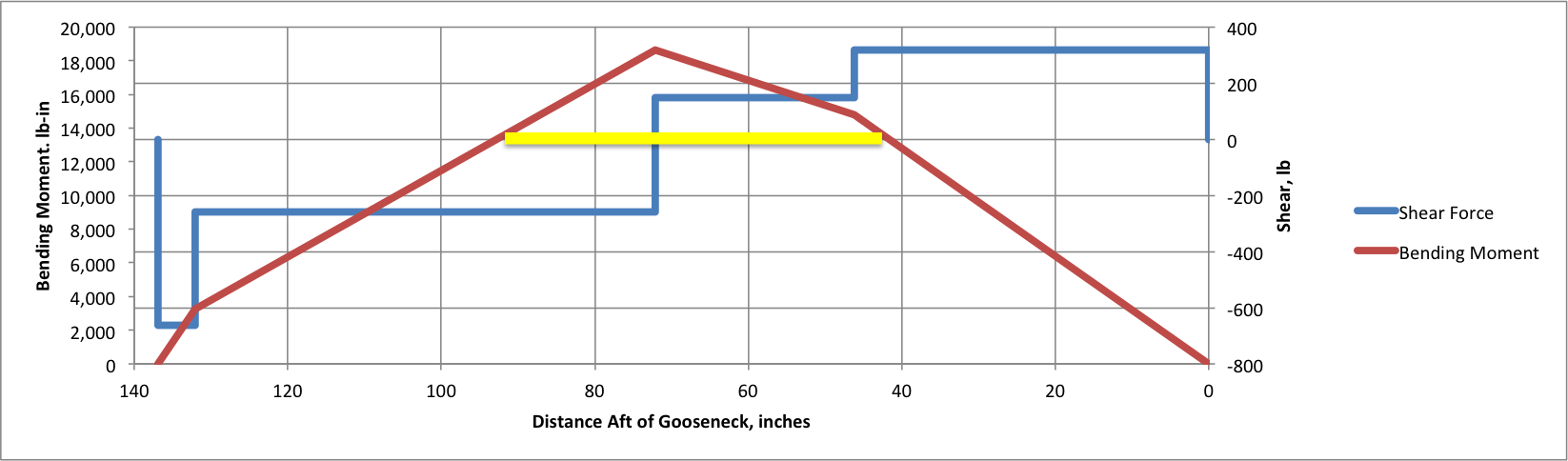
The yellow line represents the max length of the internal sleeve.
Boom Vang
I believe that I use more boom vang tension than most other people do, at least in our fleet. I set the vang tension so that when I bear away at the top mark, I keep a suitably tight main leech as I ease the main out without needed to re-adjust the vang. Currently, I have a cascading 36:1 purchase on the vang (3:1 above deck, and 12:1 below deck), but I would like to install a lever. There is too much friction in the blocks that it is hard to ease the vang off in light air, and when raising the mainsail.
Rigging the Fraculator
The fraculator pulls the top of the mast forward when sailing downwind. 99% of the boats have them. I am not sure exactly why they make the boat faster downwind, but they do.
The fraculator is comprised of a fixed ~6-foot long line attached to the jib tack at one end, with the other end hooked into the jib halyard shackle after the jib is dropped (downwind). Also, there is a shock cord retrieval segment to keep everything neatly stowed on deck when not being used.
With the fraculator attached to the jib halyard shackle (or head grommet), the jib halyard is then pulled up with all your bowman’s strength to tighten the fraculator and pull the mast forward. Pull the jib halyard sufficiently tight that the mast does not move at all in the boat as the boat pitches and rolls in the waves. The pros use the jib halyard fine tune to then get the fraculator really, really tight.
- The fraculator (frac) can be made from a small (1/8 inch to 3/16 inch (3mm to 5mm) diameter), super-strong, single braid line, such as Dynema, Vectran, or Kevlar, or something like that.
- The forward end of the frac line is tied to (or even spliced around) the jib cloth downhaul wire/line with a suitable knot (a clove hitch or maybe a better knot can be found from rigger Brian Toss) around the wire under the tack shackle.
- You want the knot as small as possible (so as to not impact the jib cloth downhaul range) and such that the knot absolutely will not slide over the tack shackle (or become untied).
- Small diameter line allows for a small knot.
- Even better than a knot might be an eye splice (i.e., brummell splice).
- The other end of the frac should have an “S” hook (or better in my view, a proper Cunningham quick release-type hook, which is what I have on my boat) so it is easy to remove from the halyard shackle when rapidly approaching the leeward mark (note: in my view, when the frac is employed, the hook should be inserted into the jib halyard shackle, not around the halyard wire).
- The length of the frac line should be such that the S-hook ends up just touching the pointy end of the cuddy cabin, or maybe a couple inches short of the point of the cuddy when the line is stretched out on deck. The one in the photo is a few inches longer than it needs to be.
- A shock cord (to keep the frac stretched out on deck when it is not being used) is then attached to a small pulley that runs along frac line (this small floating pulley needs to be put on the frac line before tying/splicing the “S” hook on the end of the line)
- The shock cord then runs through a small hole on the pointy end of the cuddy (see shock cord passing through cuddy shell in upper left side of Figure 5, above, and in Figure 7, at right), aft to a suitable termination near the spinnaker bag, or even further aft.
- I would guess you want at least 10 or 12 feet (maybe even longer) of small shock cord for this part so there is enough stretch in it for the floating pulley to easily make it to the jib tack when the frac is deployed, but still have a little tension when the frac is in the stowed position.
- Also, check out the remote release fraculator sold by Andrew “Dog” Palfrey.
Main Halyard Changeout
Ralph Carpenter
One of the quirkiest features of our boats is the main halyard lock system which secures the main halyard at the TOP of the mast. This design feature, in a couple of different forms, has been haunting Etchells sailors for years.
The purpose of the design is to reduce compression on the mast when sailing. Compression on the mast changes the bend characteristics of the mast. The mast is designed so that for a given amount of backstay pull, the forestay should tension a certain amount and the mast should bend aft a certain amount. Every Etchells rig is a little different, but this ratio is much better controlled with the mast not under compression while sailing. I am not a mechanical or marine engineer, but Skip Etchells was adamant about this design feature from the beginning. It seems most folks who have sailed Etchells for any period of time have experienced the horror of not being able to lower their mainsail because of a failure in this system and cursed this part of his design. If you find yourself in this predicament the most important thing is to find a way to get your main down before it is trashed, then find and correct the problem with the halyard/lock system so it doesn’t happen again. Seven or eight years ago I had this problem on VooDoo and luckily the riggers at Handy boat were working and one of them went up to the top of my mast in a Boson’s chair pulled by their crane, released the stuck halyard lock and lowered the mainsail. Another easy way to reach the top of your mast is to find someone with a cruising boat whose mast is at least as tall as the Etchells and pull up alongside them, send a crew member up the cruising boats mast on a boson chair then heel the Etchells over till they can grab the top of the mast and clear the problem. With the right person in the boson’s chair this takes less than 10 minutes. My Pearson 30 is always available if you need this service.
Originally on the old Kenyon masts the halyard lock was external, with a cross shaft as part of the main halyard which lodged into a yolk affair at the top of the mast. Some of you are still using this and it has its own set of issues, but the focus of this write up is on the newer Proctor and Selden/Sparcraft masts which use an internal main halyard lock (see picture) and a halyard with a small ball swaged to it 11-3/4 inches from the halyard shackle. (Note, the standard-shackle pin-to-swaged-ball length is 13.25 inches according to Chuck Poindexter at Sound Rigging in Connecticut. Why we see so many main halyards here in Casco Bay with 11.75 and 12.0 inch spacing is a mystery. – Matt) It is very important that you check for broken wire strands at this ball EVERY time you hoist your main sail. The vast majority of Etchells halyard failures take place at this swaged ball. Look carefully at the base of the ball for broken strands and if present the halyard needs to be replaced. Inspecting your halyard will give you a little bit of warning and prevent a failure while sailing which will necessitate taking your mast down and using an electrician’s snake to rethread the halyard inside the mast. This can be a very frustrating and time consuming job, and should be avoided. Assuming you found the broken strands before the halyard breaks completely it is a fairly straightforward task to attach a messenger line to the existing halyard pull it through then use it to run a new main halyard through your mast. If your existing halyard rope diameter is small enough to fit through the hole in the halyard lock you can attach the messenger line to the end of the halyard rope end at the base of the mast. This worked on Tim Tolford’s WhiteHawk last summer. If you have a large diameter line on your existing halyard you will first have to cut the old halyard at the ball and attach the messenger to that end and pull it through at the base of the mast. Once the messenger has replaced the entire halyard in the mast then attach the new halyard rope end to the messenger and pull the messenger back through from the base of the mast. Make sure the connection to the messenger is secure, even take a couple of minutes and sew the messenger to the line if in doubt. Also make sure no loose ends can get caught in the mast in the process. If you have any questions or concerns about the process seek help from a fellow fleet member. Most all of us have been through this exercise.
Etchells Halyards typically come with the ball swaged to the halyard 11-3/4 inches from the shackle (Note… the stated 11.75″ dimension may not be “standard.” Sound Rigging says that 13.25 inches is the “standard” dimension on new boats. It could be that older boats may each have a different dimension. -eds) . Measure yours before ordering to make sure it is standard. (See Comments below for a way to measure with the mast up. -eds) Also, main halyards come in two many different line diameters (for the tail). If you will be putting your halyard on with the mast up, opt for the smaller diameter line, even though it is tougher on the hands when raising the main. (I had Sound Rigging build a new main halyard using FSE Sirius 500 6mm line for the tail, which is large enough to not cut your hands when hoisting in strong winds. I was able to reeve the halyard onto my old Proctor mast with the mast stepped. My previous main halyard tail was 3 or 4mm diameter, and it was tough on the hands. -eds) The smaller diameter is made to be able to run through the opening in the halyard lock. Anything larger than ¼ inch will not pass through the lock and can only be installed with the mast down. Recently a common problem has arisen with some halyards purchased from APS or Hall Rigging. The ball swaged on the halyard needs to be pressed so that the diameter of the swage shaft that connects the ball to the cable cannot be larger than___ or it runs a high risk of jamming in the halyard lock. Prior to the 2011 World’s in San Diego 3 boats had this same problem all with brand new main halyards. To avoid this problem check the diameter of the swage before installing the halyard and if it’s too large either file it down or have it swaged again to the proper diameter. Another solution is to buy your halyards from riggers who actively sail Etchells and are aware of this problem. A few of these are Ezra Culver at EZMarine in Miami, Chuck Poindexter at Sound Rigging in Connecticut, or Marblehead Rigging out of San Diego. I trust these folks but if I obtained a halyard from anyone else I would make sure and check it before installing.
Assuming all went well with the new installation, I would attach a line to the halyard shackle and run it up and lock it a number of times before attaching the mainsail to make sure the system is functioning properly.
Many halyard locks have a slot big enough they don’t catch the swage, but if your halyard lock is tight it can be modified when the mast if finally down by filing to prevent this from happening in the future.
If you have any questions or find yourself in a jam, feel free to come to the fleet for help. We are here to help make Etchells sailing as enjoyable as possible. Give us a call or send an email and we will do our best to quickly ease your pain.
Hope this helps. Happy Sailing.
Screwdriver Tip Names
FYI…
How to get the correct main halyard ball-to-shackle pin dimension with the mast up
The correct length of the main halyard between the swaged ball and the shackle pin remains an open question. It may be that each boat has a different configuration. However, there is a straight-forward way to measure the ball-to-shackle pin dimension on a boat with the mast up, assuming there still is a functioning main halyard installed.
By rule, the mainsail luff length is 32′-6″ (maximum). The dimension from the top of a standard mainsail headboard to the bearing surface of the grommet is ~3/4 inches (I think… need to verify.)
So, attach a tape measure to the main halyard shackle, and raise it up the mast and lock the halyard. The dimension to the top of the lower limit band on the mast at the gooseneck should be 32′-6″ less 0.75″, or 32′-5.25″ (you will also need to add back in any small distance that the tape measure zero-point is above the bearing surface of the halyard shackle pin). Alternatively, you can instead attach the tape measure such that the 3/4-inch mark aligns with the bearing surface of the halyard shackle pin. Tape and/or tie the tape measure hook to the top of the shackle. Then no zero-point offset correction is necessary.
If the measured distance comes to more than 32′-6″ (or 32′-5.25″ plus the zero offset if you did not attach the tape in the alternate fashion), then your existing halyard ball-to-shackle pin dimension is too small by the difference. And vice-versa.